How to check the governor speed input on an engine in a synchronizing system?
What types of governor can I check?
This article applies to engines in a synchronizing system. These systems use a governor input to control the engine speed and hence the active power in the system when in parallel with other generators or the mains. The governor would normally be set to isochronous mode rather than droop.
This article does not apply to engines with mechanical governors, as there is no speed input and they are not suitable for synchronizing.
This article also does not apply to engines fitted with an ECU where the speed control uses the CANBUS link. Engines that use the CANBUS link for fine speed control cannot be measured in this way as the speed control signal is embedded in the the CAN data. Some engines fitted with ECU's have analogue inputs for speed control and these can be measured using this method.
Basic principles of fine speed control
Fine speed control is used to adjust the speed of the engine (or the load of the engine when in parallel). Typically the maximum adjustment via this method is about 5% of the rated speed. If your engine speed is further than 5% away from nominal, then this article may not provide the solution. See other articles on speed control and engine speed for alternative suggestions.
Fine speed control using this method is achieved with an analogue voltage output from the synchronizing controller to the engine. By far the most common is a 0-5V DC range.
The principle is that this output should be at 2.5V for nominal speed and adjust lower for a lower speed and higher for a higher speed. So for example, if the range of speed control is 5%, you might expect the engine speed to be 4% lower with a signal of 0.5V. In the rest of this article, the range used is 0-5V with a center point of 2.5V.
Note that some engines have a 'dead-zone' for voltage from 0-0.5V and 4.5-5V, in which areas the signal is considered invalid and no speed control will be performed.
Speed Control Target and Behavior In Different States
Measuring the speed control voltage is a fault finding tool to diagnose and solve issues where the engine speed is not as expected within the speed control range.
Note: Different controllers may perform differently than described in this article, which is concerned with the speed control on a DSE 8610 and a 0-5V output. For other controller models you should consult the controller documentation and engine manuals.
- With the engine speed control disconnected, the engine will sit at the speed set by the governor. there is no way for the controller to control the speed of the engine.
- With the engine speed control connected and the unit off load (breaker open) the engine will sit at the speed set by the governor, plus of minus the adjustment of SW1 (the center point, normally 2.5V).
- When the breaker is requested to be closed, the unit will try and drive itself to the nominal frequency (which is directly proportional to speed. The nominal frequency is defined in the DSE software, as per the image below.), if the first unit to close or to the frequency of the other units on the common electrical bus, if other units have already closed to the bus.
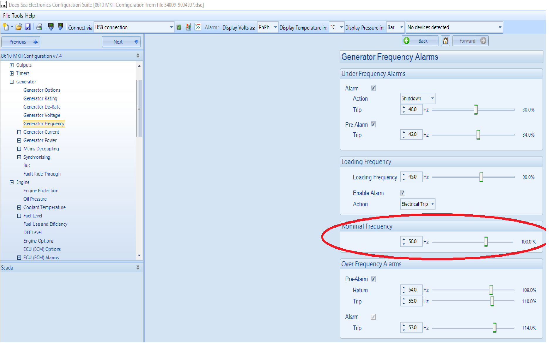
The nominal frequency is calculated from the electrical output of the alternator when running.
Sequence of Checks
Given the above three separate states and behaviors, it is suggested to fault find speed differences within the fine speed control range to perform the following steps. Note that this is a brief guide. We would recommend using the document from DSE called DSE PRODUCT GUIDE - SYNCHRONISING & LOAD SHARING (PART 1) (ENGLISH) (a login to DSE is required to download this document, but free) for a fuller overview and not to rely on this abbreviated form.
- Test the engine off load with the speed control disconnected. Confirm the engine speed is at the required nominal. If the engine speed is not at the required nominal it is not a control issue, it is an engine issue, solve before proceeding to the next step.
- Test the engine with the speed control connected, ensure the engine is running at the correct speed.
- If not at the correct speed, adjust the center point as per the DSE guide to get the engine at the correct nominal speed.
- If at the correct speed adjust the center point and ensure the engine responds to the change in speed input.
- If the engine does not respond to the center point adjustment in either case, either the engine is incorrectly configured (which if in a unit previously working is highly unlikely), the wiring to the speed controller has a fault or an electrical issue locally may have burnt out the DSE outputs.
- Run with breaker closed and confirm speed still at correct position. Monitor speed control drive (as below) as below and ensure within range. if not perform the speed control setup again as per the DSE guide above.
Governor Speed Control Drive in the Controller
Before actively measuring the speed control output, the DSE 8610 and its software can be used to view the controllers behavior. This can be views in the SCADA screen shown below and on the controller on the commissioning screen.
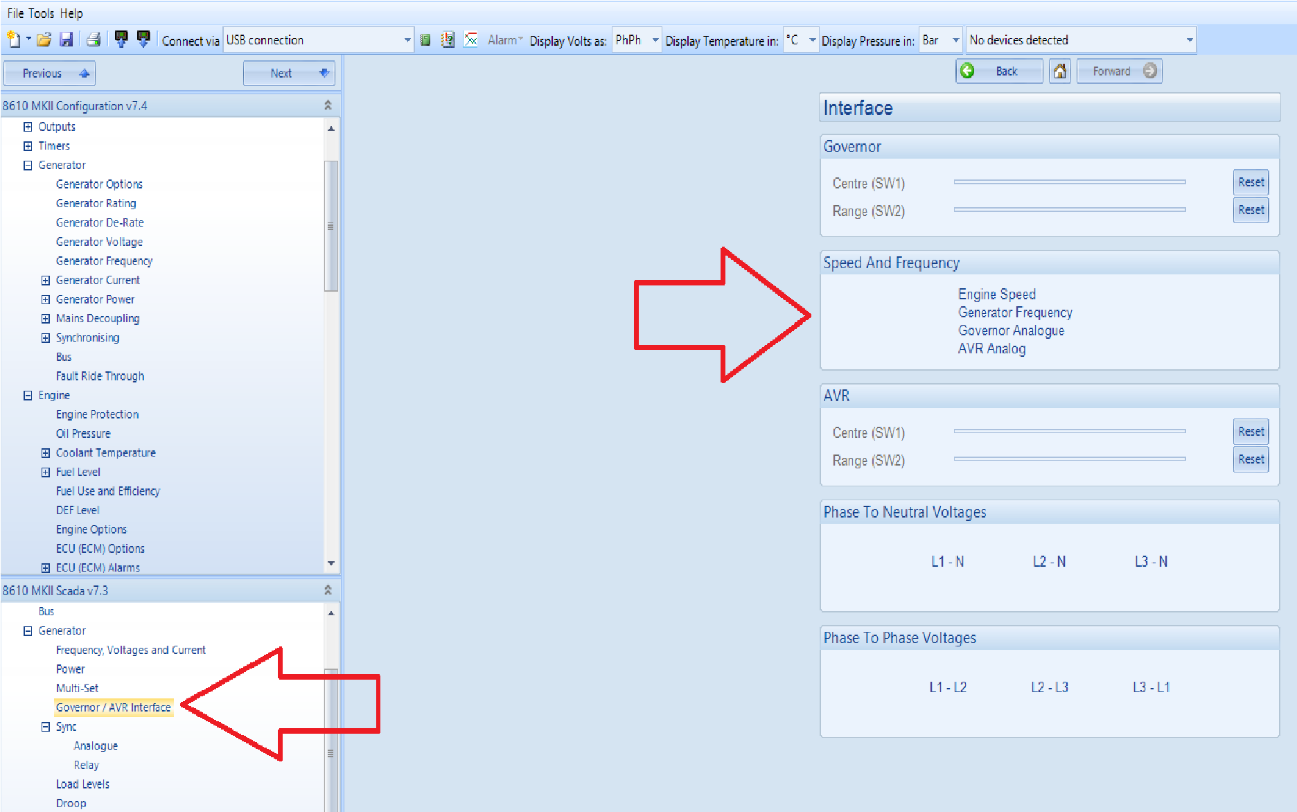
In both these areas the governor (and also the AVR for the voltage control) are shown as percentage values raging from -100% to plus 100%. The drive should be 0% when the breaker is open, as the module will only drive to the nominal frequency when the breaker is closed, or requested to close.
If the drive is nearly +/- 100%, this indicates the module is trying to drive, but there is no effect.
- Either the engine is incorrectly configured (which if in a unit previously working is highly unlikely), the wiring to the speed controller has a fault or an electrical issue locally may have burnt out the DSE outputs.
If the drive is around 0%, the module is not driving, either it thinks the unit is off load, or it is at the nominal frequency and does not need to drive.
If the drive is any value between 0-100 or 0- (-100), the unit is driving and it has hit its nominal frequency and does not need to drive anymore.
Measuring the actual voltage output from the module
In order to check that the voltage from the controller is correct it can be measured using a multimeter set to DC. To measure the output, the cables should be disconnected from the engine to get a true reading of the output.
Running off load, the voltage should be at the setting of SW1, which in our example is 2.5V DC.
In other states on load this voltage will change, to try and hit the nominal speed.